|
|
WP rail |
|
|
|
|
|||||||
|
|
|
|
|
|
||||
|
|
|
|||||||
|
|
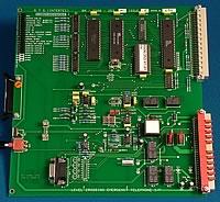
PETS Line Card, BA-6500-253 |
|
||
|
|
|
|||
|
|
|
The PETS Line Card interfaces to a Whiteley Unit located at a level crossing. The unit controls up to four Emergency Telephones sited at the crossing. The DTMF tones from the trackside Whiteley Unit are sent to the PETS Line Card. By varying these tones, the Whiteley Unit is able to transmit status information to the Concept 32 Concentrator. The PETS Line Card receives these tones and then outputs these received status signals to the PETS Alarm Card via a RS 485 interface. In the PETS Alarm Card these signals are decoded to provide the following alarms to the keypanel: •Remote power fail (Trackside Whiteley Unit). Single OFF HOOK Alarm. •Multiple OFF HOOK Alarm. •Call Tech / System Failed Alarm. N.B. The Call Tech / System Failed Alarm encompasses numerous alarm conditions that can be determined from the indicators on the PETS Alarm Card, e.g: •Vandal Alarm •DTMF Time Out Error •Equipment Fail •DTMF Checksum Error The Whiteley Unit interfaces directly to the Concept 32 Concentrator PETS Line Card eliminating the need for a second reciprocal Whiteley Unit to be located in the signal box. A concentrator requiring PETS Line Cards requires the respective location to be specifically wired for PETS. The location has a different key position from standard line cards to prevent the PETS Card being inadvertently installed in a standard line card position. Each PETS Line Card is individually addressed by a switch providing address options 0 to 7 , allowing a single PETS Alarm Card to control up to a maximum of eight PETS Line Cards. The Whiteley Unit should be configured for two-wire operation and connects to the first line of the respective PETS Line Card. Initiating a call on the keypanel will ring all four crossing telephones, therefore keys 2, 3 and 4 of the respective line card on the keypanel are not used. Conversely a call on anyone of the four crossing telephone will flash line 1 key only of the respective PETS Line Card (lines 2, 3 and 4 are unused). The PETS Line Card interfaces to the PETS Alarm Card inside the Keypanel via 15 way D type connectors, providing +12v and RS485 data to the Alarm Card. LED’s on the PETS Line Card provide system status and alarm conditions as follows: •LED 1 flashes when PETS Line Card is operational. •LED 2 indicates +12volts is available to power the PETS Alarm Card. This supply is generated from the PSU/Services card and protected by a fuse on the PETS Line Card. •LEDs’s 3 to 5 indicate call status. i.e. incoming ,outgoing or answered call. •LED 6 DTMF Tx and LED 7 DTMF Rx should be continually polling when communication with the Whiteley Unit is established. •LED 8 onwards indicate Alarm conditions. |
|
|
|
|
|
|
||